 +1 888 337 0869 [Sales]
  +1 832 318 0389 [24/7 Field Support]
 info@erdosmiller.com


Contents of this article:
- What is MWD?
- Why is MWD important?
- The 3 Building Blocks of an MWD System
- MWD Communication Protocols
- The Future of MWD
- Erdos Miller's Approach to MWD
- Featured MWD Products by Erdos Miller
What is MWD?
MWD is simply put as a system of taking measurements while drilling downhole. MWD (which stands for Measurement While Drilling) allows measurements to be sent to the surface continuously while the hole is being drilled.
Why is MWD important?
As years go by, drilling has increased all around the world and areas in which drilling is done have made drilling more complex, too. Because of this, logging has had to adapt to the new situations and technology has had to improve. The great importance of MWD comes because we need to have real-time information from the well to help with steering the drill.
The 3 Building Blocks of an MWD System
There is often a point early in the learning process where the student knows so little of the subject that they don’t even know what questions to ask. Imagine trying to teach someone who has no concept of a car (like a road cyclist) how to drive – words like ‘apply gas’ and ‘press the clutch’ and ‘you need to stay in your lane’ would have very little meaning to them because they don’t have a frame of reference for those things. Instead, the initial description might need to look something like this:
The purpose of a car is to take its passengers from one location to another. Here’s how a car works: It has four roundy wheelies to roll around on; it has an energy block (sometimes gas type and other times electric type) that makes the wheelies go round; and it has foot buttons and a turning circle that allow the driver to go forward, stop going forward, go left, and go right.
This description of a car is what some people might call a ‘gross oversimplification’ and possibly even ‘borderline condescending’. Those people would be correct. However, for someone who has no idea of what a car is, a bare-bones description like that could serve as a good primer. Nobody is going to argue that even the simplest car is orders of magnitude more complicated than what I’ve described, but the objective here is not to give technical discourse or even to answer very many questions – the objective is to give road cyclists just enough information so that they can begin asking questions and start self-navigating their learning journey.
In the same vein, the purpose of this post is not to delve into the technicals of a Measurement While Drilling (MWD) system, but to give a very high-level overview to people who have had very little to no exposure to one of the oil and gas industry’s biggest ballers. Just like with my car example above, most of what follows will be very hand-wavy and very non-technical, hopefully not to the point where it comes off as condescending.
Inertial Measurement is an important component of MWD. It is a general term for electronics that use sensors to calculate position and orientation. Pretty much all modern vehicles, from cars to airplanes, have some sort of IMU (Inertial Measurement Unit). In oil and gas, given that the IMU is the “M” in “MWD,” industry sometimes refers to this building block simply as “The MWD.”
During a drilling job, the machine operators in charge of steering the tool need to know certain things about their current position in order to make informed decisions in moving forward. Typically, this includes the wellbore’s (the hole’s) current angle of inclination as well as what direction it’s pointing relative to north. The building block of the MWD system that is responsible for taking these measurements is the Inertial Measurement Unit (IMU), which is in the wellbore. Once the measurements have been taken, the information needs to be encoded and sent up to the surface – this is the Telemetry building block. Finally, at the surface, the Surface System is used to decode and display the information that was transmitted by the IMU.
Inertial Measurement Unit – “The MWD”
“Inertial Measurement Unit (IMU)” is a general term for electronics that use sensors to calculate position and orientation. Pretty much all modern vehicles, from cars to airplanes, have some sort of IMU. In oil and gas, given that the IMU is the “M” in “MWD,” industry sometimes refers to this building block simply as “The MWD.”
Two of the primary measurements the MWD is responsible for are inclination and azimuth: Inclination is the angle of the wellbore with respect to vertical and azimuth is the angle of the wellbore’s direction with respect to North. The figures below help illustrate what these measurements look like: Inclination is simply a way of quantifying how vertical the wellbore is at a given point and azimuth is a way of describing what direction the wellbore is pointing.
When the wellbore is completely vertical, the inclination is 0° and the azimuth is undefined. When the wellbore takes a turn, the inclination begins changing from zero and, for most drilling operations, may eventually end up at 90° (horizontal). Additionally, when it changes direction from vertical, the azimuth describes that direction: If it is going North, the azimuth is 0°, if it is going East, the azimuth is 90°, etc.
Accelerometers and magnetometers are the bread and butter of the MWD. Together, these sensors can be used to measure inclination and azimuth (there are conditions when these sensors are not enough, but that deserves more attention than I’m willing to give here). Once the measurements have been taken, the MWD needs to transmit the data to the surface, where it can be interpreted by rig operators.
Telemetry
There are two primary methods for communicating information from down-hole to the surface: They include mud-pulse telemetry and electromagnetic (EM) telemetry. Both these methods have their pros and cons and various implementation challenges, however, for sake of brevity (remember, this is just a primer), only their basic theory of operation will be discussed. And we're talking Pumpkin Spice Latte Basic (PSLB).
Mud-Pulse Telemetry. During drilling, a special kind of mud (drilling fluid) is pumped down the tubing and then sent back to the surface. Electronics at the bottom of the hole drive a valve that can constrict and relax the flow of this mud, creating pressure pulses in the fluid that’s circulating in and out of the hole. These pressure pulses are the heart of mud-pulse telemetry (more on what happens with these pulses later).
To learn more about Mud-Pulse Telemetry, Encoding and Decoding M-ARY, and some examples, check this guide:

EM Telemetry (Electromagnetic Telemetry). Most people don’t usually think of the earth as being a conductor and might be surprised to find out that it is. Maybe not as good of a conductor as a piece of copper, but a conductor, nonetheless. At any rate, the earth’s conductive properties can be taken advantage of for data transmissions. If you have some special electronics known as an ‘EM Transmitter’ at the bottom of the hole, you could stick two probes in the rock and send a sinusoidal signal through the earth, up to the surface (more on what happens with these signals later).
Typically, only one of these methods are implemented at a given time. It’s important to know which one is being used, because the surface system needs to know what type of signal it should be expecting (If you designed an MWD system with an EM transmitter and a mud-pulse surface system, you would be pretty embarrassed!)
Surface System
The purpose of the surface system is to receive the data transmitted from downhole and to display that information in a way that is meaningful to the rig operators. If the method of telemetry is mud-pulse, the surface system will include a pressure transducer that detects the pressure pulses in the drill fluid and converts the pulses to electrical signals; electronics are designed to convert these electrical signals into ones and zeros. If the MWD at the bottom of the hole did its job right, the ones and zeros received at the surface will be able to be decoded and give meaningful information.
In the case of EM Telemetry, electronics are designed to detect the sinusoidal signal that was transmitted from the bottom of the wellbore. The challenge with this is that, by the time the signal travels from the bottom of the hole to the surface, it will have lost most of its power to the earth and the electronics need to be able to amplify it in a way that it can be identified amidst the noise that will inevitably creep in. Like mud-pulse telemetry, the EM transmitter is responsible for encoding data into the signals that are transmitted and, when those signals are received at the surface, they will be able to be decoded and give meaningful information.
For either mud-pulse or EM telemetry, once ones and zeros are received, they are sent to a special computer called a Rig Floor Display (RFD), where the information is decoded and displayed. RFD’s are special because of the way that they are (again, I invoke PSLB to justify this appalling explanation). The rig operators can then use information (such as, but not limited to, inclination and azimuth) to make decisions on how to move forward in their drilling operations.
The three building blocks of an MWD system encompass the getting of information, the transmitting of information, and the receiving of information. The success of any drilling operation relies on these blocks to function seamlessly, both independently as well as with each other. This post did not provide a lot of details on how that is accomplished, but, hopefully, it did provide enough information to outline some of the major objectives in designing electronics for oil and gas – and, when you’re learning to drive, it helps to know what a car is!
What about MWD Communication Protocols?
Since inception, one of our passions at Erdos Miller has been designing and developing measurement while drilling (MWD) tools. These tools are an engineer’s dream given their complexity and the intense challenge of designing one that works reliably time and again.
Many years ago, the Tensor corporation brought to market the first affordable mass market MWD system. The company took the capabilities that only a few of the majors, like Schlumberger, Halliburton, and Baker Hughes possessed and made an affordable system for the mass market. Thousands were sold, and this system quickly became the working standard for smaller service companies, with many compatible third-party replacement components being developed.
The qMIX/qBUS Communication Protocol
Like most complex systems, there was a need for machine-to-machine communications. The engineers at Tensor chose to implement a custom serial protocol of their own and called it qMIX, also known as qBUS, q/BUS, q/MIX, or sometimes just q. Given that the Tensor systems became the working standard, qMIX also became the standard communication protocol.
Even though these tools were developed many years ago, they are still prevalent today, and to successfully develop MWD equipment compatible with a wide array of today’s tools, one must master qMIX. However, mastering qMIX and developing compatible software is a challenge. Little to no documentation exists so you’re left on your own. You need to break out an oscilloscope, decode the communication by hand, and reverse engineer the operation of this complex communications protocol byte by byte.
Bus Architecture
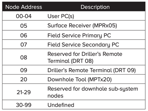
The qMIX protocol defines the procedures for communications over a multipoint link where two or more processors are connected. The bus is controlled by a communications bus master (CBM) which arbitrates all bus traffic. Nodes on the bus have a unique ID number in the range of 00-99. The bus master cycles through the address space polling each node and the addressed node may transmit data at this time if it is available. Data transfers between nodes are relayed through the bus master rather than directly from node to node.
The protocol allows for one node to relinquish bus master status to another node, but in practice few nodes have the capability of being bus master; examples include MPUs and some surface receivers. Data is transferred using predominantly ASCII characters, although binary data transfers are also possible.
To learn more about the qMIX/qBUS Communication Protocol, you can download this guide, in which you will find:
- How the Bus architecture is defined and controlled.
- The Bus Communication Protocol: polling sequences, calling sequences, and message broadcasts.
- How the fields are structured: Header, Data, and CRC.
- All information laid out simply, using examples.

How does the future of MWD look like?
Erdos Miller conducted a survey to better understand the MWD landscape, surveying a total of 103 respondents. The respondents from the industry consisted of business owners, operations/product managers, R&D, technology, and many more.
Lots of measurements have been required for the industry within the last 10 years on top of your standard measurements. The requirements are going to continuously go up including more data or possibly adding LWD (Logging While Drilling) sensors. More health measurements will also possibly be needed and maybe even integration of Rotary Steerable Systems. These are a few trends that we can predict for the future of MWD:
We need more MWD tools and innovation:
According to the MWD2021 survey, almost half of the people from the industry using MWD tools believe that tools with the functionalities they need are still not on the market, or the ones that are out there still need to go through some innovation:
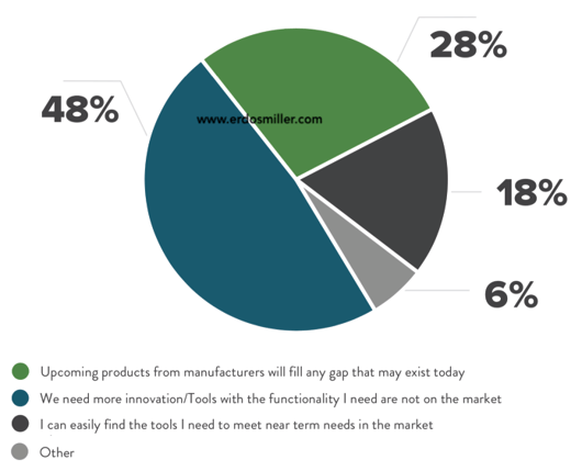
This market has always produced a unique conflict. We want new technology with the same level of reliability and risk as the old one. Trying something new has always been difficult. As everyone looks to the future, it will be fascinating to see what OEMs come up with for the solutions.

The drilling industry cannot live without the dynamics measurements provided by MWD systems:
When asked, 35% of workers and decision-makers from the drilling industry said the dynamic measurements acquired by today's MWD systems are invaluable to them, and they cannot imagine running a job without them.
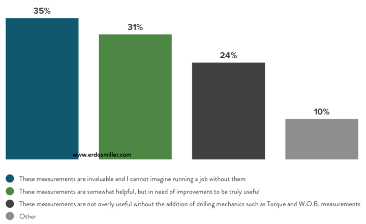
Drilling Dynamics measurements from the MWD have become an invaluable tool for most service companies and operators. The boundaries can continue to be pushed to deliver even more useful and intuitive information from these sensors.
Download the MWD2021 Report to learn more about the general perception on what the future of MWD will look like for the industry. Inside of the report you will find:
- The general perception of 103 respondents about current MWD tools and manufacturers.
- A breakdown of the survey in 9 main questions with split answers.
- What the industry is expecting from the future MWD Technology in the next few years.
- Powerful insights by Ken Miller, Co-Founder at Erdos Miller.

Erdos Miller's approach to MWD:
Erdos Miller takes a technology forward approach to the MWD industry. We value innovation that allows for more accurate well placement while reducing tortuous
Our experience
We have a vast experience working on:
- Directional Modules
- Power Supplies
- Pulser Drivers
- PWD Modules
- Azimuthal Gamma
- EM Telemetry
- 175C Board Design
Partnership Opportunities
- Wireless Short-hop (Project Ongoing)
- High-Speed Mud Pulse Telemetry
- Magnetic Ranging System
- High Temperature Gyro Module
Featured MWD Products by Erdos Miller:
At Erdos Miller, we have always been passionate about developing great measurement while drilling technology. We believe MWD operators deserve great technology and believe that sensors should be cost effective and easy to use, while being built on cutting edge technology.
Here are some of our products:
The MicroPulse MP2 (135°C) [Directional Sensor]
The MicroPulse directional controller utilizes state of the art MEMS accelerometers and magnetometers to deliver high accuracy directional measurements. Every MicroPulse sensor is ISCWSA (Revision 4) MWD Error Model compliant . The MicroPulse directional controller integrates the directional sensors, dynamics measurements, and MWD telemetry into a single rugged low power module.

_tilt-right.png?width=459&name=ErdosMiller_MP3-(transparent)_tilt-right.png)
The MicroPulse MP3 (150°C) [Directional Sensor]
The MicroPulse directional sensor uses state of the art solid state accelerometers and magnetometers to deliver highly accurate directional measurements. Every MicroPulse 3 sensor meets the ISCWSA Standard Error Model limits.

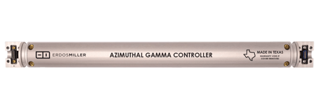
The Azimuthal Gamma Controller (150°C)
The Azimuthal Gamma Controller (AGC) brings azimuthal gamma measurements to probe-based MWD systems. Most commercially available focused gamma sensors are supported for flexible system configurations. Focused gamma sensors can be mated directly to the AGC and provide measurements on pin 8, 11, or 12. Real-time measurements available over qMIX or CAN allow for real-time geosteering decisions to be made, while a high-resolution16-bin image is logged to memory for post-run analysis.

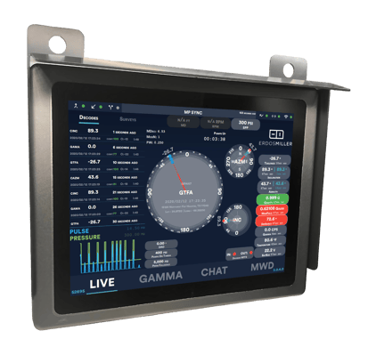
PulseTouch MWD Surface System [Receiver]
The PulseTouch is a 'plug-and-play' system containing high powered intel processors for guaranteed, built-in processing power. It has an intuitive user interface designed from the ground up with the end-user in mind and remote-ops compatibility. Pulse Touch uses a proprietary algorithm optimizing pressure pulse decoding by intelligently choosing between 100+ filtering options.

Can’t find what you’re looking for or need more information?
Contact us to learn more!

 15120 Northwest Fwy.